Cpcu 520 pdf. The CPCU ® 520 exam is the second CPCU ® exam in a series of eight required exams to complete your CPCU ® designation. This exam consists of 75 multiple choice questions split up into two sections: 49 part A questions (concept questions) and 26 part B questions (case questions). CPCU - Chartered Property & Casualty Underwriter. CPCU 520: ebook & Online Question Bank (3rd Edition) $70.00. CPCU 520 Package 3rd Edition - Package 1 includes an ebook and Online Question. Learn insurance test cpcu 520 with free interactive flashcards. Choose from 174 different sets of insurance test cpcu 520 flashcards on Quizlet. Start studying CPCU 520 Practice Test Questions. Learn vocabulary, terms, and more with flashcards, games, and other study tools. The CPCU ® 520 exam consists of 75 multiple choice questions broken up into two sections, part A and part B. Part A: Concept questions – The first section of the exam will be approximately 49 concept questions; these questions.
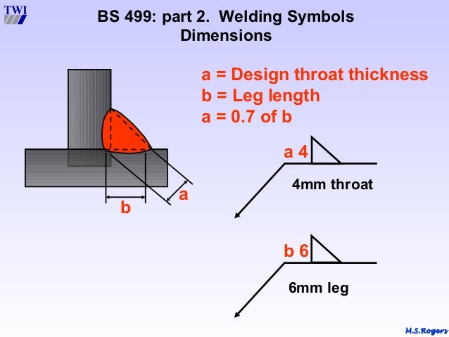
1) an equal leg fillet weld in a 90 degree joint the width of the face is 2 times that of the throat. So if you can only measure the face AND the leg sizes are equal you can approximate the throat. 2) If you can only measure the smallest leg, the throat will be.707 times that dimension. 3) You can only use a throat gage on a flat or concave weld.
Formulae_IndexNomenclature
Weld Throat Thickness Eurocode

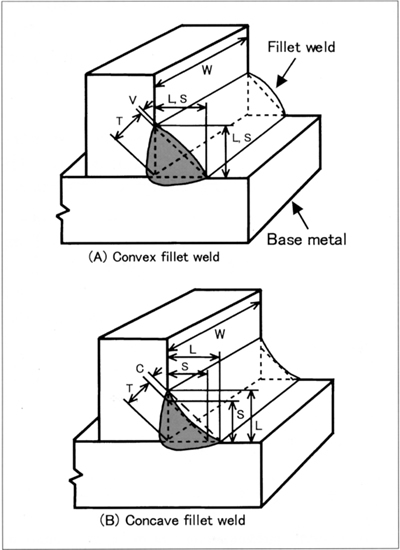
- The strength of a fillet weld is based, in the design, on the product (effective area of the weld: T×W) of the theoretical throat (design throat thickness) and effective weld length as shown in Fig. Fillet weld legs determine fillet weld sizes. Fillet weld sizes are measured by the length of the legs of the largest right.
- Theoretical Throat Concave Fillet Weld Size of Weld. = 1.4 tn or the thickness of the hub, whichever is smaller, but not less than 1/8 in.
- Section J2.2a wherein the effective throat thickness is considered to be equal to the weld size for 3/8-in. And smaller welds, and equal to the effective throat thick-ness plus 0.11 in. For fillet weld sizes over 3/8 in.' For example, assume a weld throat of 0.45 in (11 mm) is required. A standard 5/8 in (16 mm) fillet weld will achieve this.
Introduction... Relevant Standards... Variables Associated With Welds...
Guidance Principles... Table Basic Weld Calcs... Assessment of Fillet Welds...
Examples of Fillet Welds Calcs... Properties of Fillet Welds as lines...
Example of torsion weld calc. using vectors... Capacities of Fillet Welds... Design Strength of Fillet Welds...
| Introduction The following notes are general guidance notes showing methods ofcalculation of the strength and size of welds. Welded joints are oftencrucially important affecting the safety of the design systems. It isimportant that the notes and data below are only used for preliminary designevaluations. Final detail design should be completed in a formal wayusing appropriate codes and standards and quality reference documents Relevant Standards BS 5950-1:2000 .Structural use of steelwork in building. Code of practice for design. Rolled and welded sections BS EN 10025-1:2004 - Hot rolled products of structural steels. General technical delivery conditions Variables related to welded joints
Guidance Principles A generous factor of safety should be used (3-5) and if fluctuatingloads are present then additional design margins should be included to allow for fatigue The table below provides provides approximate stresses in, hopefully, a convenientway. Table of bracket weld subject to direct and bending stresses
Assessment of Fillet Weld Groups ref notes and table Properties of Fillet Welds as lines Important note: The methods described below is based on the simple method of calculationof weld stress as identified in BS 5950- clause 6.7.8.2 . The other method identifed in BS 5950 - 1 clause 6.7.8.3as the direction method uses the method of resolving the forces transmittedby unit thickness welds per unit length into traverse forces (FT ) andlongitudinal forces (FL ). I have, to some extent,illustrated this method in my examples below Examples of Fillet Weld Calculations
Properties of weld groups with welds treated as lines - It is accepted that it is reasonably accurate to use properties based onunit weld thickness in calculation to determine the strength of welds as shown in the examples onthis page. The weld properties Ixx Iyy and J are assumedto be proportional to the weld thickness. The typical accuracy of this method ofcalculation is shown below.. This is illustrated in the tabled values below
Note: The error identified with this method is lower as h increasesrelative to d. Watch kiss x sis ova episode 1. This error is such that the resulting designs are conservative. Example illustrating use of stress vectors
Note: The example above simply illustrates the vector method adding direct and torsional shear stresses and compares the differencein using the unit weld width method and using real weld sizes. The example calculates the stress levels in an existing weld groupit is clear that the weld is oversized for the loading scenario. The difference in the resulting values are in less than 4%. If the welds were smalleri.e 3mm then the differences would be even smaller. Table properties of a range of fillet weld groups with welds treated as lines -
Table Of Weld Capacities The fillet weld capacity tables related to the type of loading on the weld. Twotypes of loading are identified traverse loading and longitudinal loading as show below The weld loading should be such that { (FL/PL) 2 + (FT/PT) 2 } ≤ 1 The following table is in accord with data in BS 5950 part 1. Based ondesign strengths as shown in table below .. Design Strength PL = a.pw PT based on elements transmitting forces at 90o i.e θ = 45o and K = 1,25
Design Strength p w of fillet welds
|

Useful Related Links
|

- The strength of a fillet weld is based, in the design, on the product (effective area of the weld: T×W) of the theoretical throat (design throat thickness) and effective weld length as shown in Fig. Fillet weld legs determine fillet weld sizes. Fillet weld sizes are measured by the length of the legs of the largest right.
- Theoretical Throat Concave Fillet Weld Size of Weld. = 1.4 tn or the thickness of the hub, whichever is smaller, but not less than 1/8 in.
- Section J2.2a wherein the effective throat thickness is considered to be equal to the weld size for 3/8-in. And smaller welds, and equal to the effective throat thick-ness plus 0.11 in. For fillet weld sizes over 3/8 in.' For example, assume a weld throat of 0.45 in (11 mm) is required. A standard 5/8 in (16 mm) fillet weld will achieve this.
Introduction... Relevant Standards... Variables Associated With Welds...
Guidance Principles... Table Basic Weld Calcs... Assessment of Fillet Welds...
Examples of Fillet Welds Calcs... Properties of Fillet Welds as lines...
Example of torsion weld calc. using vectors... Capacities of Fillet Welds... Design Strength of Fillet Welds...
| Introduction The following notes are general guidance notes showing methods ofcalculation of the strength and size of welds. Welded joints are oftencrucially important affecting the safety of the design systems. It isimportant that the notes and data below are only used for preliminary designevaluations. Final detail design should be completed in a formal wayusing appropriate codes and standards and quality reference documents Relevant Standards BS 5950-1:2000 .Structural use of steelwork in building. Code of practice for design. Rolled and welded sections BS EN 10025-1:2004 - Hot rolled products of structural steels. General technical delivery conditions Variables related to welded joints
Guidance Principles A generous factor of safety should be used (3-5) and if fluctuatingloads are present then additional design margins should be included to allow for fatigue The table below provides provides approximate stresses in, hopefully, a convenientway. Table of bracket weld subject to direct and bending stresses
Assessment of Fillet Weld Groups ref notes and table Properties of Fillet Welds as lines Important note: The methods described below is based on the simple method of calculationof weld stress as identified in BS 5950- clause 6.7.8.2 . The other method identifed in BS 5950 - 1 clause 6.7.8.3as the direction method uses the method of resolving the forces transmittedby unit thickness welds per unit length into traverse forces (FT ) andlongitudinal forces (FL ). I have, to some extent,illustrated this method in my examples below Examples of Fillet Weld Calculations
Properties of weld groups with welds treated as lines - It is accepted that it is reasonably accurate to use properties based onunit weld thickness in calculation to determine the strength of welds as shown in the examples onthis page. The weld properties Ixx Iyy and J are assumedto be proportional to the weld thickness. The typical accuracy of this method ofcalculation is shown below.. This is illustrated in the tabled values below
Note: The error identified with this method is lower as h increasesrelative to d. Watch kiss x sis ova episode 1. This error is such that the resulting designs are conservative. Example illustrating use of stress vectors
Note: The example above simply illustrates the vector method adding direct and torsional shear stresses and compares the differencein using the unit weld width method and using real weld sizes. The example calculates the stress levels in an existing weld groupit is clear that the weld is oversized for the loading scenario. The difference in the resulting values are in less than 4%. If the welds were smalleri.e 3mm then the differences would be even smaller. Table properties of a range of fillet weld groups with welds treated as lines -
Table Of Weld Capacities The fillet weld capacity tables related to the type of loading on the weld. Twotypes of loading are identified traverse loading and longitudinal loading as show below The weld loading should be such that { (FL/PL) 2 + (FT/PT) 2 } ≤ 1 The following table is in accord with data in BS 5950 part 1. Based ondesign strengths as shown in table below .. Design Strength PL = a.pw PT based on elements transmitting forces at 90o i.e θ = 45o and K = 1,25
Design Strength p w of fillet welds
|
Useful Related Links
|
